Step-by-Step Guide: How to Sketch Custom Railings in Less Than 3 Minutes
Discover how sketching mode in a 3D railing configurator reduces site planning from days to minutes while aligning sales and engineering in one system.

Every custom railing project starts messy. Photos, PDFs, markups, and quick sketches move between teams while the layout keeps changing. And before anyone can design the railing, the project is already stuck in back-and-forth.
That’s why our manufacturing product configurator includes a dedicated sketching mode. Instead of jumping straight into railing configuration without understanding the space, users can quickly sketch the site and define the layout.
In this quick step-by-step guide, we walk through how a simple site sketch becomes a structured railing layout that can instantly turn into a 3D model. All in under three minutes.
Prefer a video walkthrough? You can follow the same workflow in this video.
Why Sketching Mode Makes a Big Difference
In real projects, layout always comes before the product. But many digital tools still push users straight into component choices. Pick a profile, choose an infill, define spacing, set posts. That sounds logical, but it clashes with how projects actually unfold on site.
At the start, contractors, installers, and sales teams often know the space better than the final railing details. They know where the deck is, where the stairs sit, and how people will move through the site. Product decisions however, are still open.
The sketching mode in our manufacturing product configurators matches that reality. Instead of starting with railing details, the configurator starts with the shape of the site. Users draw a structured layout of a deck, balcony, or stair run using simple and intuitive UI.
This is not a freehand doodle. It is a smart sketch that’s connected to real product logic, structural constraints, and business rules. That shift changes the workflow in three practical ways:
- Sales get clarity in minutes instead of chasing PDFs.
- Engineering receives cleaner, more logical inputs.
- The jump from 2D idea to 3D model happens without redrawing everything.
This approach works especially well for:
- Custom railings for decks, balconies, and terraces
- Stair rail systems with elevation changes
- Perimeter layouts around patios or pools
- Modular outdoor structures like pergolas or balustrades
Let’s take a look at the 5 easy steps to build custom railings with sketching mode.
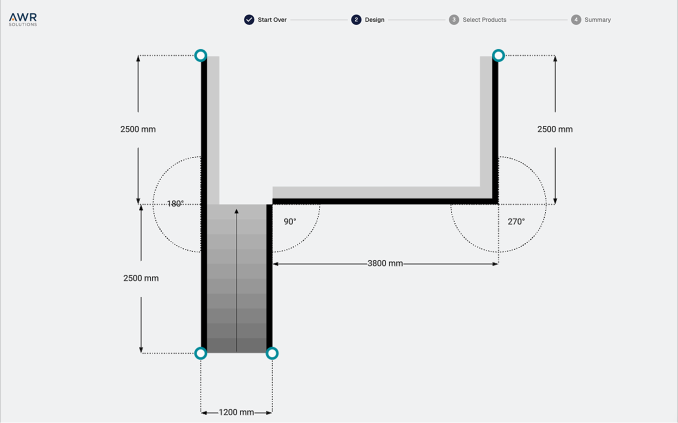
Step 1 - Start Sketching the Layout
The process begins on an empty canvas or from a predefined preset layout. At this stage, nothing is being configured yet. The goal is to sketch a site plan, either from scratch or by starting with a structured template that reflects common project types.
Sketching mode is designed to work for many kinds of layouts. In this example we are outlining a deck made of flat surfaces and stairs. But you can use the same approach for room layouts, pergolas, modular cabinets, or any project where a shape needs to be defined before configuring details.
We begin with a flat surface. Once selected, we enter sketching mode. By dragging on the canvas, a flat surface section is created. Clicking again immediately continues the sketch without changing tools, so the drawing flows seamlessly.
Sketching can be stopped at any time by pressing Escape or clicking Done. When this happens, the layout clearly displays two open endpoints where we can add new pieces.
Why this matters: starting from a blank canvas removes product friction upfront. It helps users think clearly about the site itself before technical decisions come into play.
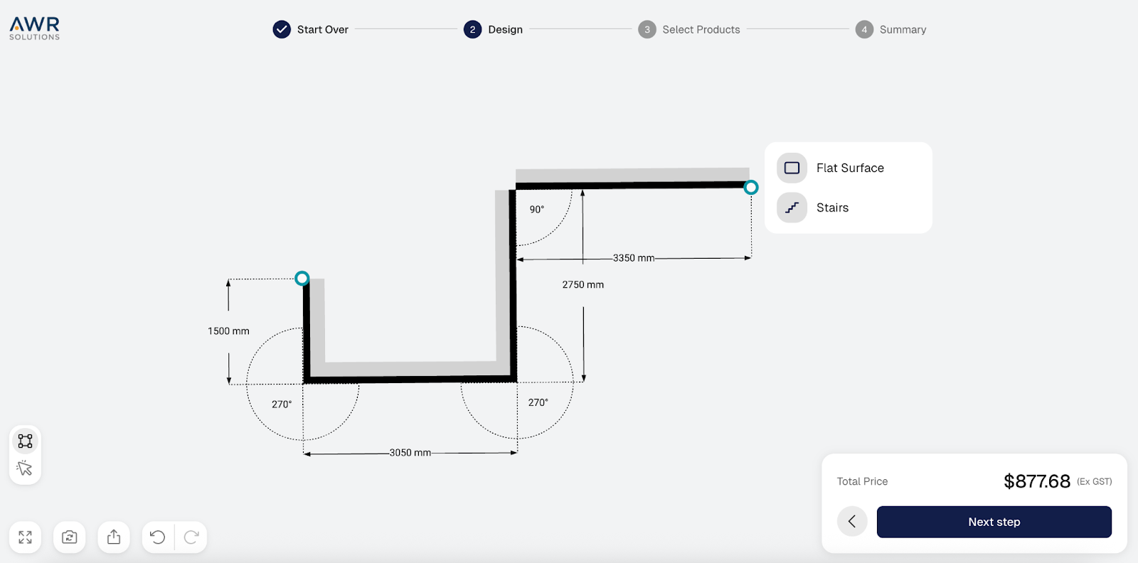
Step 2 - Add Stairs and Complete the Shape
From any open endpoint, we can introduce stairs. Stair segments follow their own geometric and structural rules, including rise, run, angle, and connection constraints.
As soon as stairs are added, the system automatically recalculates available starting points and connection options based on those parameters. Every angle and transition respects the underlying product logic and structural limits.
This makes it possible to represent real sites with elevation changes without manually recalculating or redrawing anything.
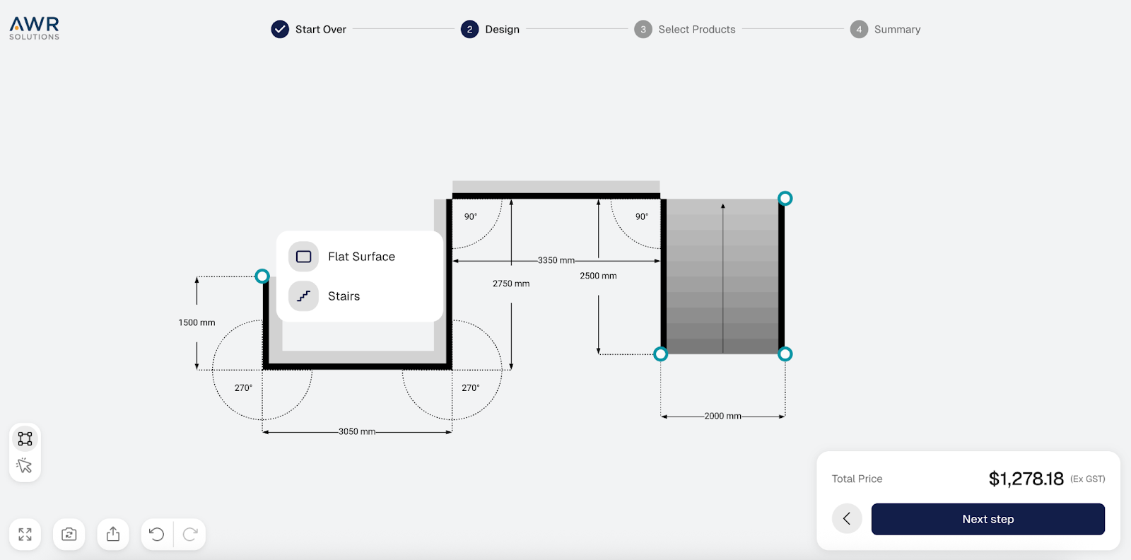
After placing stairs, we continue sketching additional flat surfaces until the overall deck or balcony shape feels complete.
By the end of this step, the basic outline of the site is usually complete. The perimeter and stair run are visible, and the relationships between all pieces are clear.
Why this matters: most delays in real projects come from unclear layouts. This step creates a shared, structured picture of the site in under a minute.
Prefer a video walkthrough? Watch the video below:
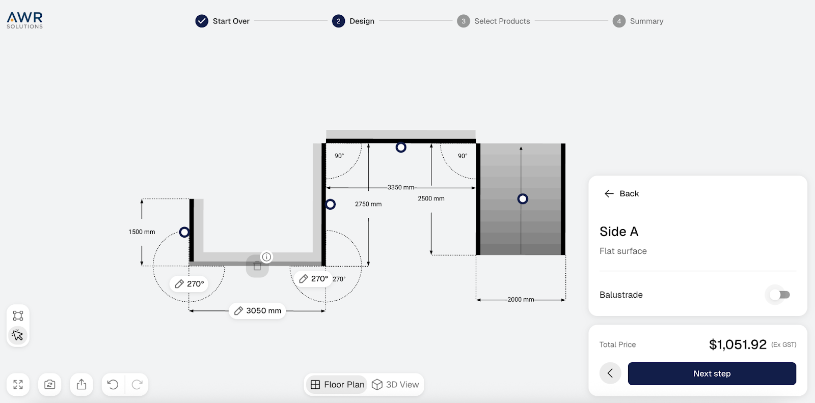
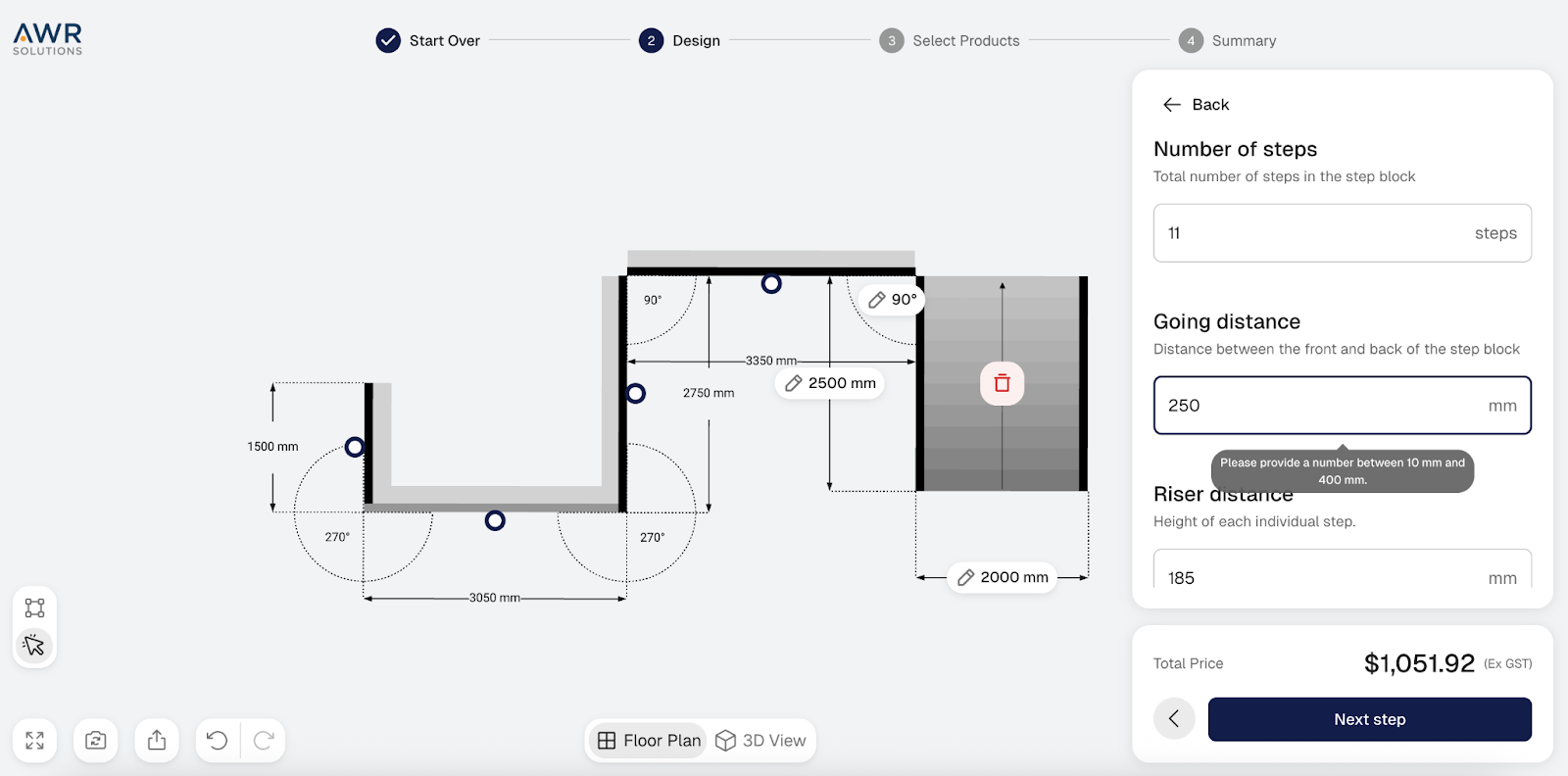
Step 3 — Switch to Selection Mode and Fine-tune
Now the workflow moves from sketching to selection mode. This is where a quick outline becomes a usable plan.
By selecting any flat surface, its properties can be edited. This includes:
- toggling the balustrade on or off,
- deleting a section if needed,
- changing its dimension, and
- adjusting the connection angle.
If something is modified, for example changing a length, the configurator automatically adjusts all connected sections. Everything remains properly linked.
The same applies to angles. When we change an angle, neighboring segments shift accordingly, without breaking the layout.
Undo and redo are always available, which makes it easy to test variations safely.
Why this matters: this is where sketching mode proves its value. Instead of redrawing everything when a detail changes, the layout adapts smartly, saving time for sales and engineering teams.
Step 4 — Quick Adjustments to Stairs if Needed
Stairs provide additional options beyond flat surfaces. We can change their dimension, and any geometry attached to them remains connected and valid.
This flexibility makes it easier to match real site layouts, even when they are not perfectly straight or symmetrical. The configurator flexes with the site instead of forcing the site to fit the tool.
Why this matters: small tweaks to stairs often determine whether a layout works in practice. Being able to adjust them quickly prevents costly rework later.
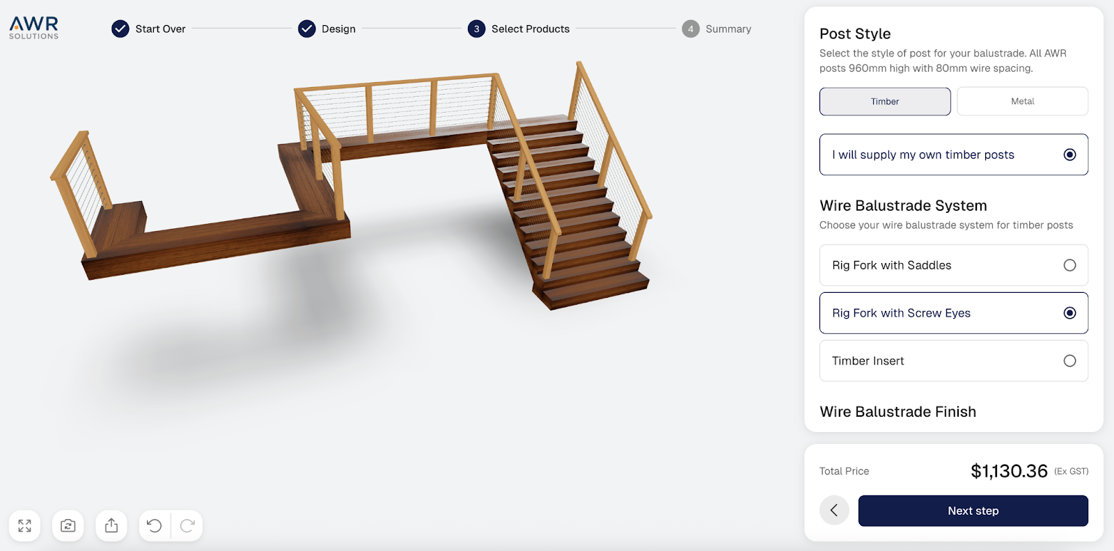
Step 5 — Switch to 3D and Let Parametric Models Take Over
Once the sketch is complete, we switch into 3D. This is where the configurator’s parametric models take control.
Flat surface sections align cleanly even at custom angles, so unusual layouts still come together without gaps or overlaps. Stairs follow parametric rules as well. If the number of stairs changes, the design, spacing, and patterns update correctly.
Wrapping up: What Changes When You Sketch First
Sketching first does not just save time. It changes how teams work together. Teams work together using one shared digital layout in the 3D configurator. This avoids passing files back and forth. When the site changes, the model adapts instead of being rebuilt.
The result is less interpretation, fewer redraws, and a much faster path from rough idea to a usable plan.
Traditional workflow vs. 3D configurator with sketching:
Once the site is captured as structured data instead of scattered drawings, everything moves faster. Teams no longer interpret files; they work from the same model. That single shift explains why minutes replace days in the comparison above.
If you want to see how this works in practice, watch the demo below:
Want to See How We Can Build a Manufacturing Product Configurator With Sketching Mode for Your Business?